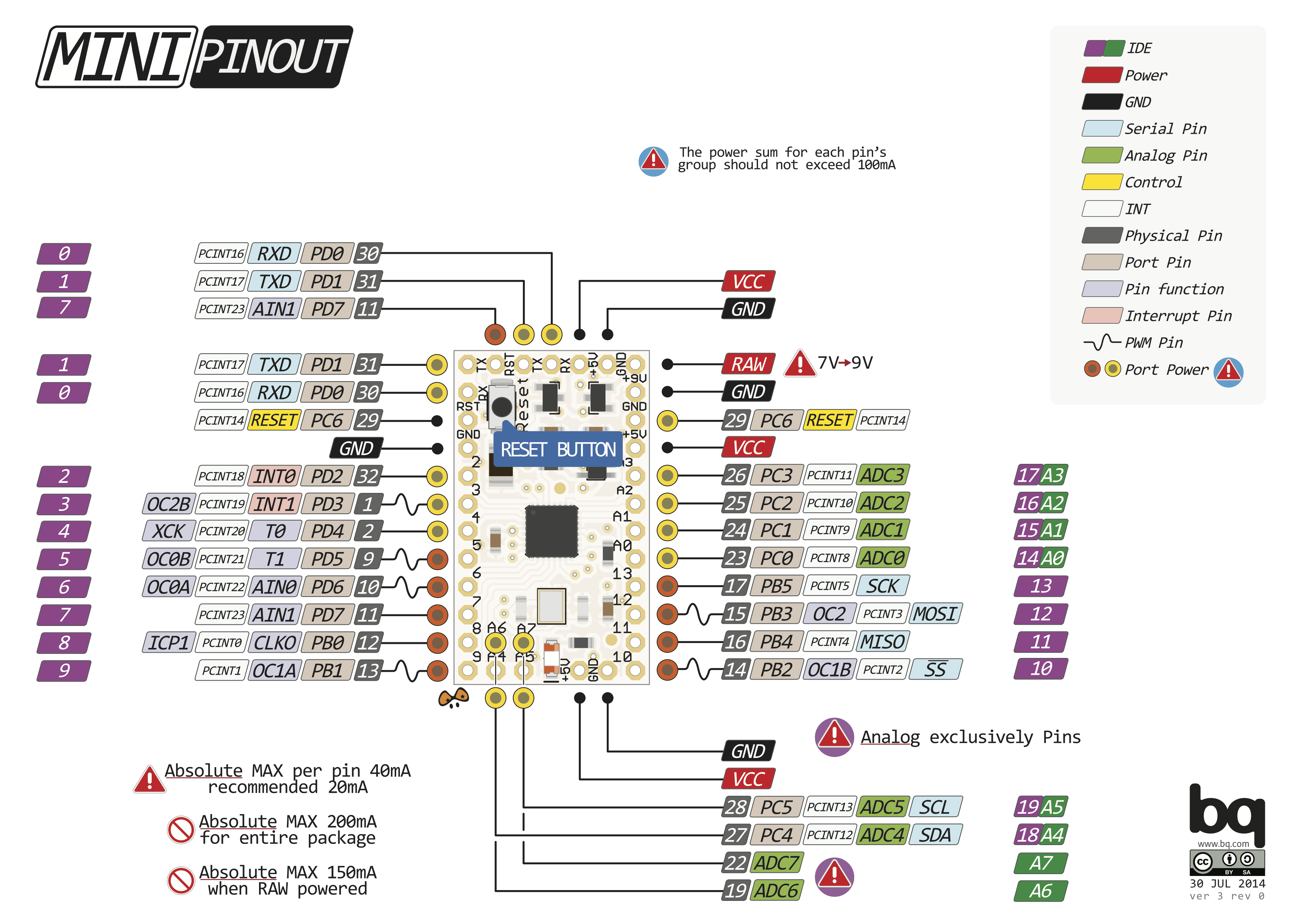

- #ARDUINO PRO MINI PINOUT DIAGRAM HOW TO#
- #ARDUINO PRO MINI PINOUT DIAGRAM PDF#
- #ARDUINO PRO MINI PINOUT DIAGRAM SOFTWARE#
- #ARDUINO PRO MINI PINOUT DIAGRAM SERIES#
#ARDUINO PRO MINI PINOUT DIAGRAM SERIES#
The input impedance at A0 is 330Kohm (probably true for all such boards), so if you want to increase the max voltage further, you can add a resistor in series with A0 R = Vmax * 100-330 K.

Some of the development boards add a potential divider network usually to make the sensitivity 3.3v at the A0 pin, I only have direct experience of the NodeMCU board where this is the case, but it might also be true of the products you mention. Yes, the bare chip has a maximum voltage of 1v, of course it is possible to increase that with a simple potential divider network (2 resistors, one of which is probably already on your chip/board). If you’re getting started with the ESP8266, we have some great content you might be interested in: We also have a similar guide for the ESP32 GPIOs that you can read.
#ARDUINO PRO MINI PINOUT DIAGRAM HOW TO#
If you have some tips on how to use the ESP8266 GPIOs properly, you can write a comment below.

We hope you’ve found this guide for the ESP8266 GPIOs useful.
#ARDUINO PRO MINI PINOUT DIAGRAM SOFTWARE#
Usually, the following GPIOs are used as I2C pins:ĮSP8266 allows software PWM in all I/O pins: GPIO0 to GPIO15. The ESP8266 doens’t have hardware I2C pins, but it can be implemented in software. Learn how to put the ESP8266 into deep sleep mode: To wake up the ESP8266 from deep sleep, GPIO16 should be connected to the RST pin. GPIO16 can be used to wake up the ESP8266 from deep sleep. Most of the ESP8266 development boards have a built-in LED. ESP8266 ADC – Read Analog Values with Arduino IDE, MicroPython and Lua.You can learn how to use analog reading with the ESP8266 with the following guide: If you’re using a development board like the ESP8266 12-E NodeMCU kit, the voltage input range is 0 to 3.3V because these boards contain an internal voltage divider. The maximum input voltage of the ADC0 pin is 0 to 1V if you’re using the ESP8266 bare chip. That GPIO is called ADC0 and it is usually marked on the silkscreen as A0. The ESP8266 only supports analog reading in one GPIO. GPIO4 and GPIO5 are the most safe to use GPIOs if you want to operate relays. You can read this article that investigates the state and behavior of each GPIO on boot. The following GPIOs output a HIGH signal on boot:Īdditionally, the other GPIOs, except GPIO5 and GPIO4, can output a low-voltage signal at boot, which can be problematic if these are connected to transistors or relays. This may be problematic if you have relays or other peripherals connected to those GPIOs. There are certain pins that output a 3.3V signal when the ESP8266 boots. GPIO1: pin is high at BOOT, boot failure if pulled LOW.GPIO2: pin is high on BOOT, boot failure if pulled LOW.The following list shows the state of the following pins on BOOT: The ESP8266 can be prevented from booting if some pins are pulled LOW or HIGH. So, these pins are not recommended to use. GPIO6 to GPIO11 are usually connected to the flash chip in ESP8266 boards. LabelĬonnected to FLASH button, boot fails if pulled LOWĬonnected to on-board LED, boot fails if pulled LOWĭebug output at boot, boot fails if pulled LOWĬontinue reading for a more detailled and in-depth analysis of the ESP8266 GPIOs and its functions. The pins highlighted in red are not recommended to use as inputs or outputs. The ones highlighted in yellow are OK to use, but you need to pay attention because they may have unexpected behavior mainly at boot. The pins highlighted in green are OK to use. The following table shows the correspondence between the labels on the silkscreen and the GPIO number as well as what pins are the best to use in your projects, and which ones you need to be cautious. For example, D0 corresponds to GPIO16 and D1 corresponds to GPIO5. One important thing to notice about ESP8266 is that the GPIO number doesn’t match the label on the board silkscreen.
#ARDUINO PRO MINI PINOUT DIAGRAM PDF#
We’ve put together a handy PDF that you can download and print, so you always have the ESP8266 diagrams next to you:ĭownload PDF Pinout Diagrams » ESP8266 Peripherals Download PDF with ESP8266 Pinout Diagrams


 0 kommentar(er)
